


1. Function principle, advantages, and limitations of strain transducers:
Strain transducers, such as HBM’s SLB, have proven their value in many measurement tasks. They can be easily attached to existing structures with screws. Typical applications include presses, welding machines, silos, etc. For instance, when a press stroke is initiated in a press equipped with a strain sensor, it results in a strain in the press frame that is proportional to the pressing force. The strain transducers convert this strain into a measurable electrical signal that enables the force, in this case, the force exerted by the press, to be derived.
The advantages of strain transducers are clear:
- A strain sensor is available at a considerably lower price than a force sensor; this applies, above all, when compared with force transducers for use with large forces
- Strain sensors do not impact the system’s stiffness. Hence, the machine’s dynamic properties do not get affected
- Force transducers for use with very large forces, especially, require some additional space. This means that the measurement system’s structure is modified, which presents a problem, especially if it is to be offered only as an option
However, set against these advantages are some drawbacks:
- Strain sensors are in no way as accurate as force sensors. This is a crucial factor, as there is an increasing demand for higher accuracy in production
- Strain transducers must be calibrated after mounting. Calibration means that the force exerted in the process first needs to be measured with a force sensor, such as the C6A. It is then compared with the strain transducer’s signal and subsequently, the strain is converted into a force. The calibration can also be performed using known weights. In this case, the accuracy of the subsequent measurement cannot be better than the accuracy of the calibration process
2. Strain transducer with integrated electronics:
Strain transducers are often the first choice when accuracy is not the top priority, and the budget for the measurement system is limited. In this case, the sensor needs to be complemented with amplifier electronics, a key component that requires an investment to be made and sufficient space to be reserved.
This is why HBM has fitted the SLB strain transducer for simple measurement tasks with highly effective electronics. This sensor is available with both a 4...20 mA output and a 0...10 V output; the additional code, “VA” (SLB700A/06VA), is appended to its type name.
Whenever the parallel connection of multiple strain sensors is not desired, it is particularly advisable to use the SLBVA. Whenever a parallel connection is absolutely necessary, it is recommended to examine whether the SLB700A passive strain transducer without integrated electronics might be the better choice.
Connecting strain transducers in parallel:
In many applications, it is desirable not to measure the potential bending strain. The bending strain can be easily compensated for using two strain transducers. To achieve this, the strain transducers need to be mounted on a symmetrical component, exactly opposite each other, and electrically connected in parallel. The SLB700A passive strain transducers are suitable for this purpose as, with these models, the output resistance and the sensitivity have been balanced. Another advantage is that the SLB strain transducers have a high input resistance of 1000 Ω. Even if four sensors are connected in parallel, the resistance of the bridge amplifier is only 250 Ω — a load that most amplifiers can easily supply.
The decision whether to use a strain transducer with or without integrated electronics also depends on the demands that are placed on signal conditioning. It is advisable to check whether the functions provided by an industrial measuring amplifier are required, such as filter algorithms, limit value switches, or computation channels.
Strain transducers with an integrated amplifier are the ideal choice whenever the measured value is to be acquired without a parallel connection, mathematical functions are not required (or implemented in a control device), and a cost-effective solution is desired.

SLB700A/06VA active strain transducer with integrated electronics for extremely high forces.
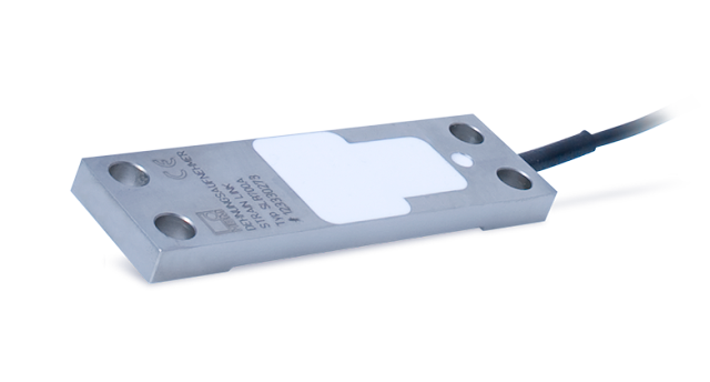
SLB700A strain sensor - a cost-effective sensor for indefinitely high forces.
3. HBM’s “Teach” method: Maximum output signal, irrespective of the application:
Conventional strain sensors with a built-in amplifier module have a non-adjustable amplification — for instance, 500 µm/m correspond to an output signal of 10 V. However, the maximum output signal depends on the given amplification, which cannot be changed. When the sensor in the example mentioned above is subjected to a strain of 200 µm/m, the resulting output voltage is 4 V (500 µm/m = 10 V, accordingly, 2 V per 100 µm/m). Particularly, when the next element in the measurement chain is a module that has a low resolution or increased noise, for instance, because existing components are to be used, the results are often unsatisfactory.
HBM’s SLBVA active strain sensors with integrated amplifier electronics manage to bypass this problem, as they provide the maximum possible output signal at any time, irrespective of the intended purpose.
This sensor type has a total of five (current version) or six (voltage version) inputs and outputs:

With the current version, the measuring circuit is closed via the supply voltage’s 0V input (black wire). Let us now look at the so-called “Teach2 input, IN2. This input allows the sensor to be adjusted to virtually any measuring range.
To achieve this, HBM has developed a very convenient method, the so-called “Teach” method:
- First, the sensor is installed in the usual manner, and the load on the machine (press, roll stand, silo) is reduced to zero. A prolonged pulse (at least + 10 V) on the “Teach” input is sufficient to have the electronics save the zero point
- Subsequently, the maximum load is applied and another SHORT pulse (at least 10 V, shorter than one second) is sent to the “Teach” input. The electronics are then adjusted between these two points
It is easy to see that this method enables the input range of the next level to be fully utilized because the maximum output range is available, irrespective of the strain level.
4. More tips and tricks about the “Teach” method:
With the “Teach” method, there is always a buffer of 10% in the upper and lower parts of the measuring range. Higher strain signals, for instance, in the event of a failure are amplified and transmitted. The electronics, thus, are not set between 0 and 10 V but between 1 and 9 V.
The characteristic curve, i.e., the ratio of the strain and the output signal, can also be negative. Both shortening and elongation can be converted into a positive signal. Therefore, it makes no difference whether a shortening (negative strain) or an elongation (positive strain) is considered, as the integrated electronics can convert both strains into a positive output signal. The decisive factor is the point which is acquired first and defined as the zero point. The built-in measuring amplifier provides low noise and a bandwidth of 2 kHz and is thus well-suited for dynamic processes.
It is essential to permanently store the span, i.e. the difference between the minimum (the zero point) and the maximum (the maximum force applied). The zero point, on the other hand, is not permanently stored and it gets lost after a power failure. Therefore, it is imperative to reset to zero after a power failure. However, a re-calibration is not necessary.
It should also be noted that there is a lower strain limit to which the sensor can also be calibrated. This limit makes sense since otherwise, the electronics’ noise might become too strong. The zero position and the strain at the maximum applied force must always differ by 50 µm/m. A smaller difference results in the electronics failing to complete the teach-in process. With steel structures, this corresponds to a material stress of approximately 10 N/mm2 which facilitates its use even with very low strain levels, i.e., with very stiff structures.


Interested? Submit your enquiry using the form below:
Only available for registered users. Sign In to your account or register here.